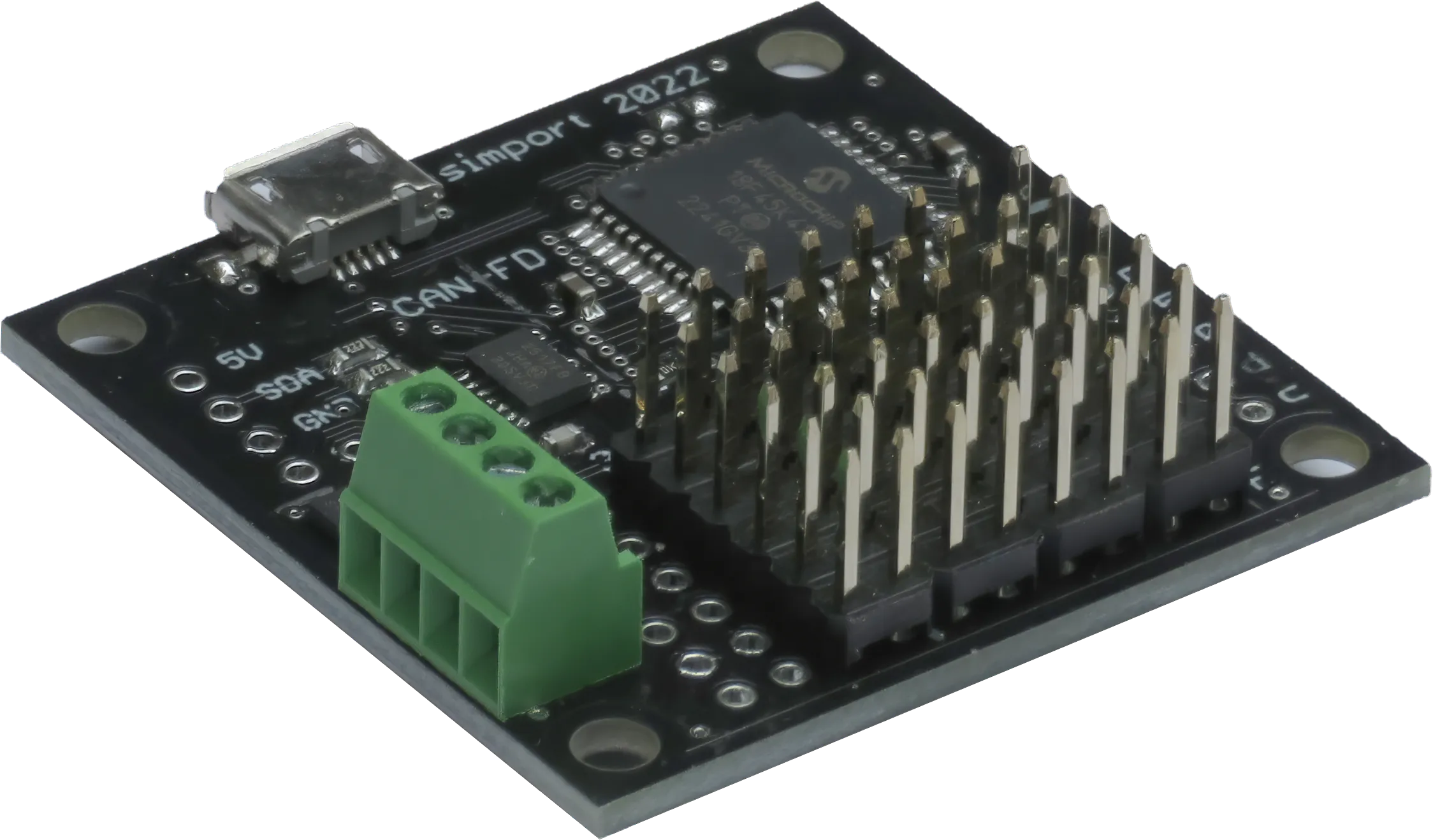
Digital Output Module

The digital output module offers a versatile solution with 24 output pins that can be configured in either push-pull or open-drain mode.
The current state of all digital outputs can be preserved, allowing for seamless reconstruction upon the next power-up.
Each pin is capable of sourcing or sinking up to 50 mA of current. However, it's important to note that the total current across all pins should not exceed 250 mA to ensure proper operation and avoid overloading the module.
| Byte | Description | Values |
|---|---|---|
| 0 | Node ID | 1-255 |
| 1 | Data Type | 11 (BCHAR) |
| 2 | Service Code | <port pin num> |
| 3 | Message Code | <message num> |
| 4 | Data Byte 1 | pin state <bit field> |
| 5 | Data Byte 2 | 0 |
| 6 | Data Byte 3 | 0 |
| 7 | Data Byte 4 | 0 |
| Bit | Description | Values |
|---|---|---|
| 0 | Port Pin LOW | Set to 1 for pin state LOW |
| 1 | Port Pin HIGH | Set to 1 for pin state HIGH |
| 2-7 | unused | 0 |
Digital output modules use CAN Identifiers in the range of 0x728 - 0x72F.
