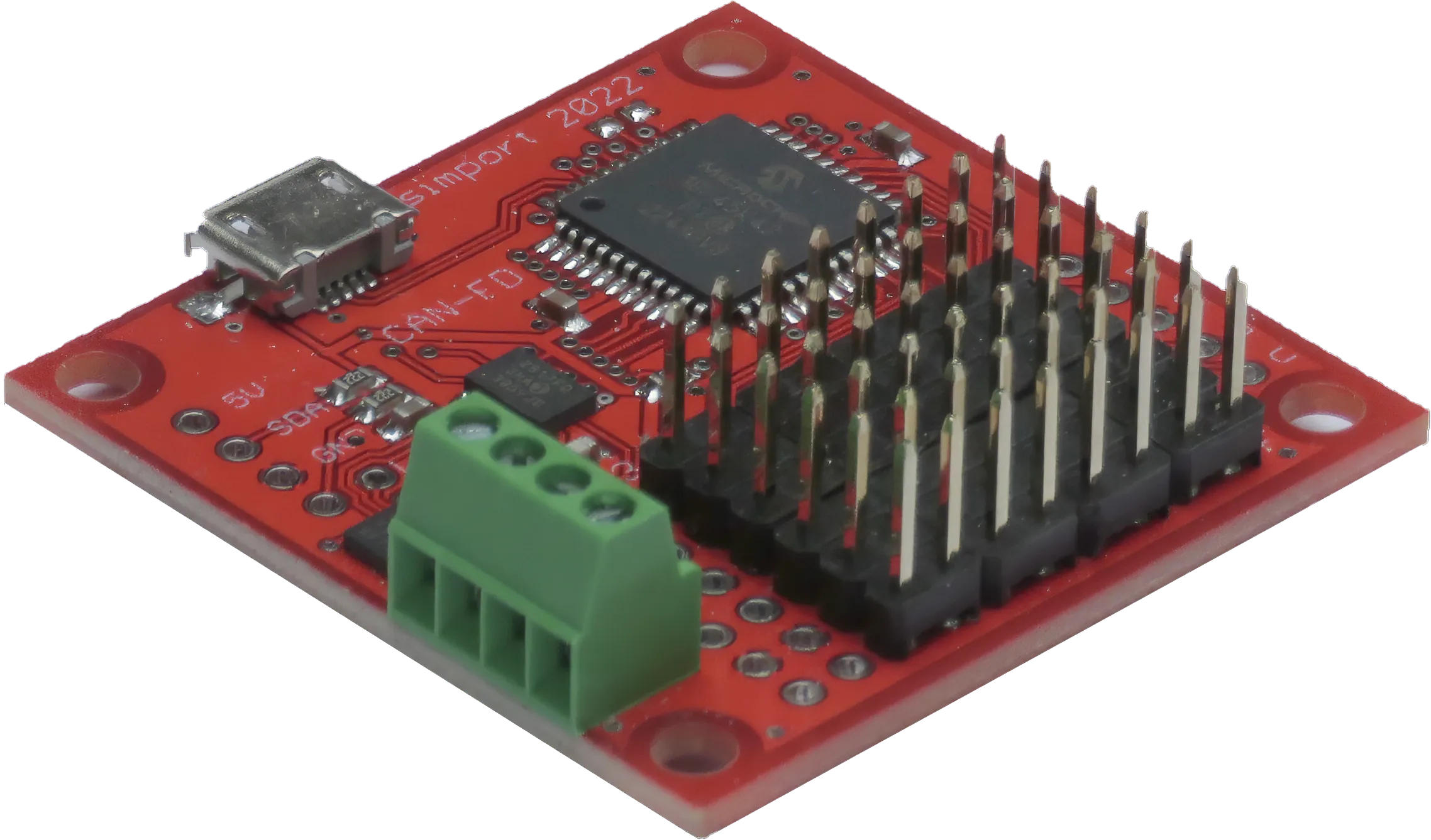
Keyboard Module

The keyboard module is equipped with 24 inputs designed for simple switches, pushbuttons, or contacts. When an input is pulled to ground (i.e., the switch is closed), it generates a key-down message on the CAN bus. Conversely, when the input is released, a key-up message is generated. Each input can be assigned a unique keycode associated with a possible modifier (such as shift, ctrl, alt, gui), allowing it to produce keystrokes similar to a standard keyboard.
The USB interface accepts these messages and converts them into HID reports for compatibility with keyboard devices.
When a non-zero keycode byte is detected, it signifies a "key down" event. In contrast, a keycode of zero specifically denotes a "key up" event, indicating the release of the key.
The keyboard module can be programmed using a CanAerospace node service, the Module Configuration Service (MCS), which can be accessed through the USB interface.
The structure of the CAN bus data field sent by an encoder module is as follows:
| Byte | Description | Values |
|---|---|---|
| 0 | Node ID | 1-255 |
| 1 | Data Type | UCHAR2 (19) |
| 2 | Service Code | <keypad num> |
| 3 | Message Code | <message num> |
| 4 | Data Byte 1 | <modifier bit field> |
| 5 | Data Byte 2 | <keycode> |
| 6 | Data Byte 3 | 0 |
| 7 | Data Byte 4 | 0 |
| Bit | Description | Values |
|---|---|---|
| 0 | LEFT CTRL | Set to 1 if the left Ctrl key is pressed |
| 1 | LEFT SHIFT | Set to 1 if the left Shift key is pressed |
| 2 | LEFT ALT | Set to 1 if the left Alt key is pressed |
| 3 | LEFT GUI | Set to 1 if the left Gui key is pressed |
| 4 | RIGHT CTRL | Set to 1 if the right Ctrl key is pressed |
| 5 | RIGHT SHIFT | Set to 1 if the right Shift key is pressed |
| 6 | RIGHT ALT | Set to 1 if the right Alt key is pressed |
| 7 | RIGHT GUI | Set to 1 if the right Gui key is pressed |
The <keycode> (Data Byte 2) refers to one of the keycodes defined in the USB HID Usage Tables, Table 10, Keyboard Page Link .
You can find a table here that provides the key usages (aka keycodes).
Keyboard modules use CAN Identifiers in the range of 0x720 - 0x727.
